VOID9 Macropad handwiring guide
Intro and BOM
The 3d models used in this handwiring guide can be downloaded either from Thingiverse or Github.
Before we start putting things together, lets go over the bill of materials:
- 3d printed case parts
- 9 Cherry MX style mechanical switches
- 9 diodes (tme.eu)
- 9 keycaps of choice
- 1 Pro Micro (Aliexpress)
- 0.5 mm wire
- hotglue
- 4 M3x10 Allen head bolts (tme.eu / 13mm overall length, 5,5mm diameter head)
- 4 8mm bumpons
If you're feeling bold, or if you think that it could be useful, you can swap one (or more) keys for an EC11 rotary encoder. If you plan on doing that, you'll also need this incredibly helpful 3d printed adapter and a knob.
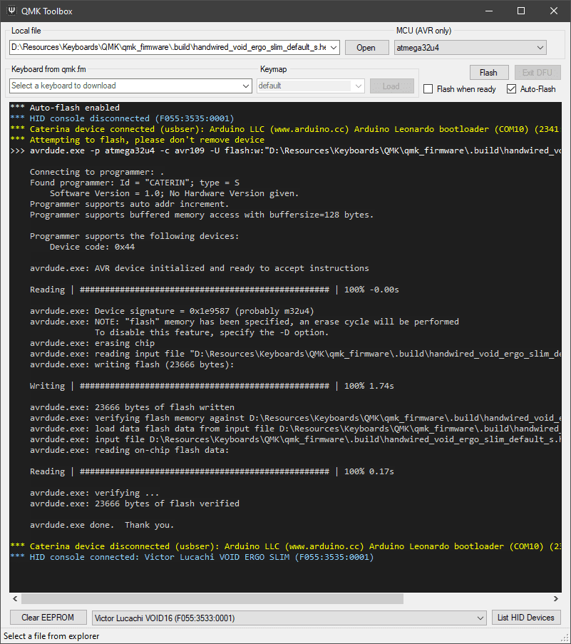
Right now would be a good time to flash your Pro Micro; the VOID9 needs only six pins, but it's good practice to flash the controller before anything else, in order to avoid any unpleasant surprises (a broken controller) later on.
Pro Micros (and clones) use Adafruits Caterina bootloader by default; when they are externally reset, by bridging the RST and GND pins, they start in bootloader mode and wait for 8 seconds before going back to user mode.
After the firmware is compiled from my fork of QMK, it can be flashed with QMK Toolbox, by selecting the .hex file, enabling the Auto-Flash option and resetting the controller via the RST and GND pins.
Macropad wiring and assembly
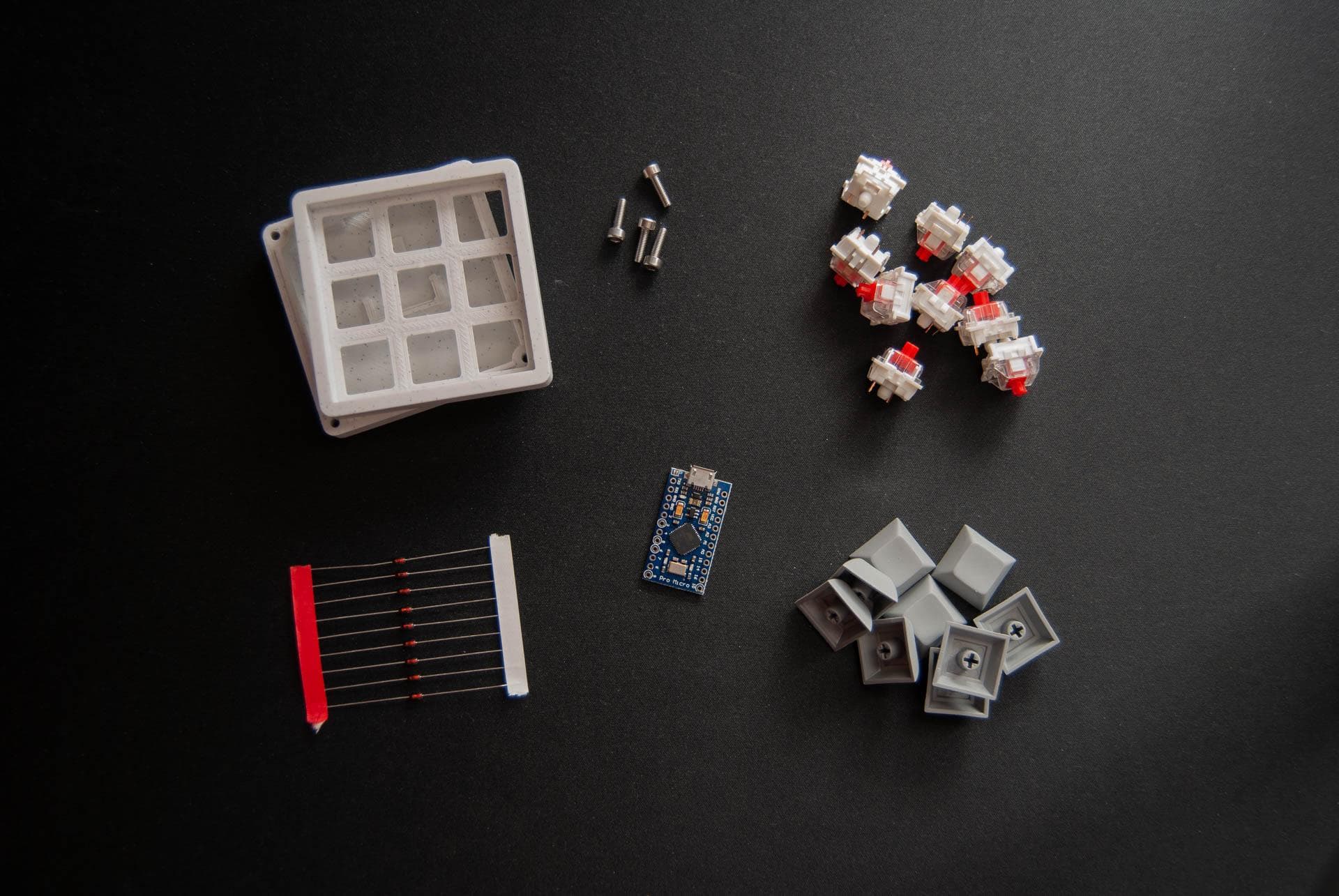
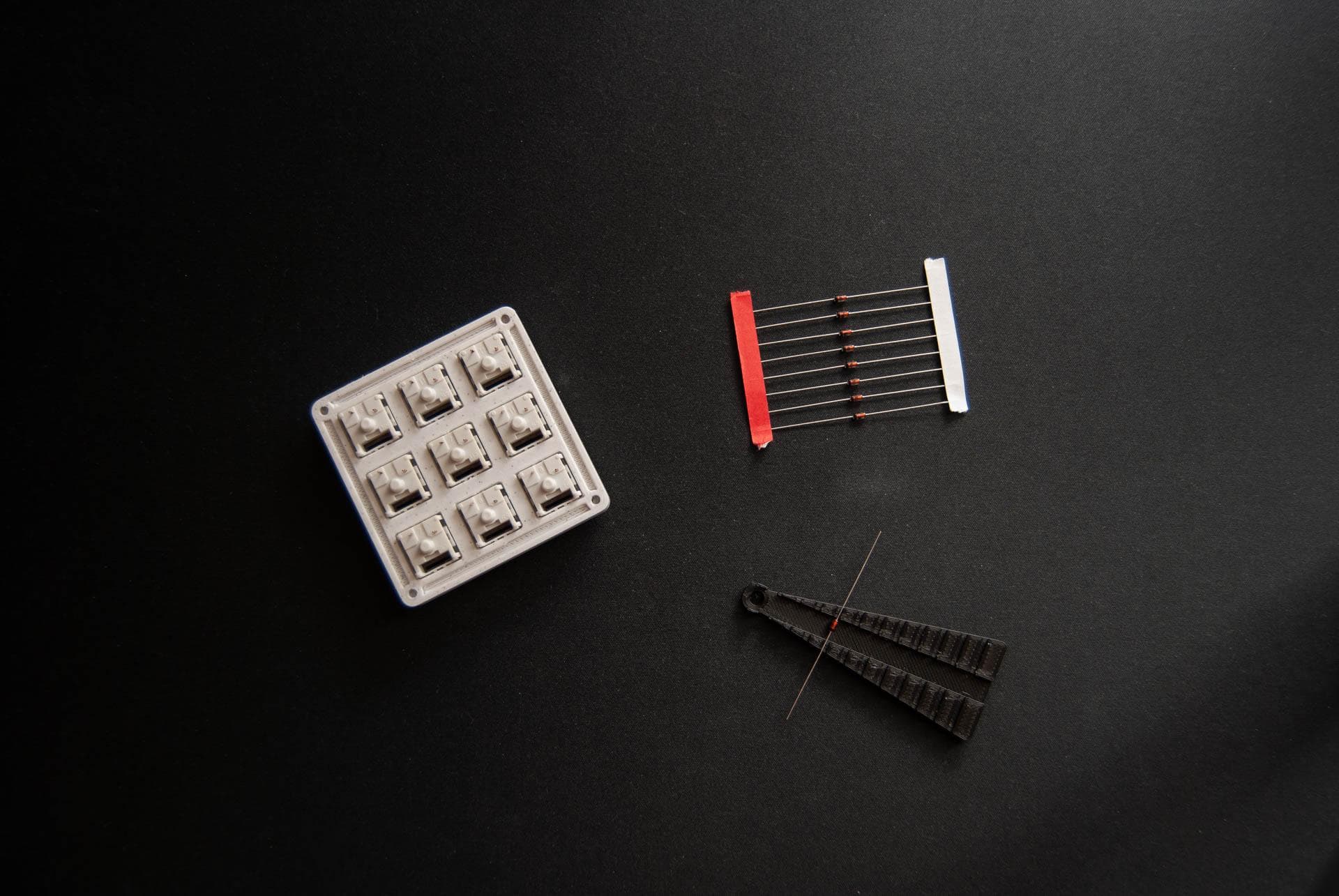
Now that the controller is flashed and ready to go we can proceed to the actual wiring and assembly of the macropad. Pictured below are most of the parts needed for this build.
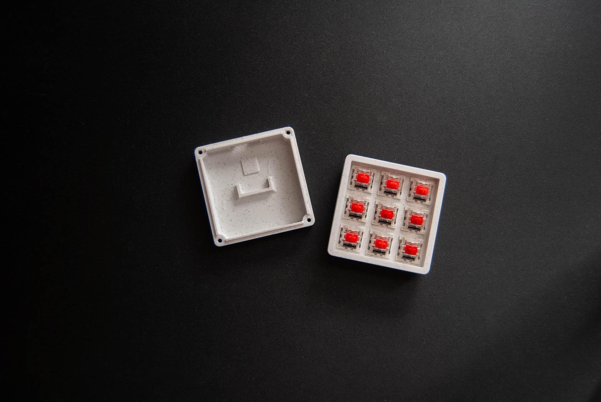
1. Inserting the switches in the top plate
Depending on how well calibrated the 3d printer is, the switches should pop into the plate/top part of the case and have no play; if they do move around a bit, it can be fixed later with small dabs of hot glue around the switches, on the inner part of the case.
2. Bending the diodes
Once the switches are pushed in firmly and they sit flush with the plate it's time for diodes.
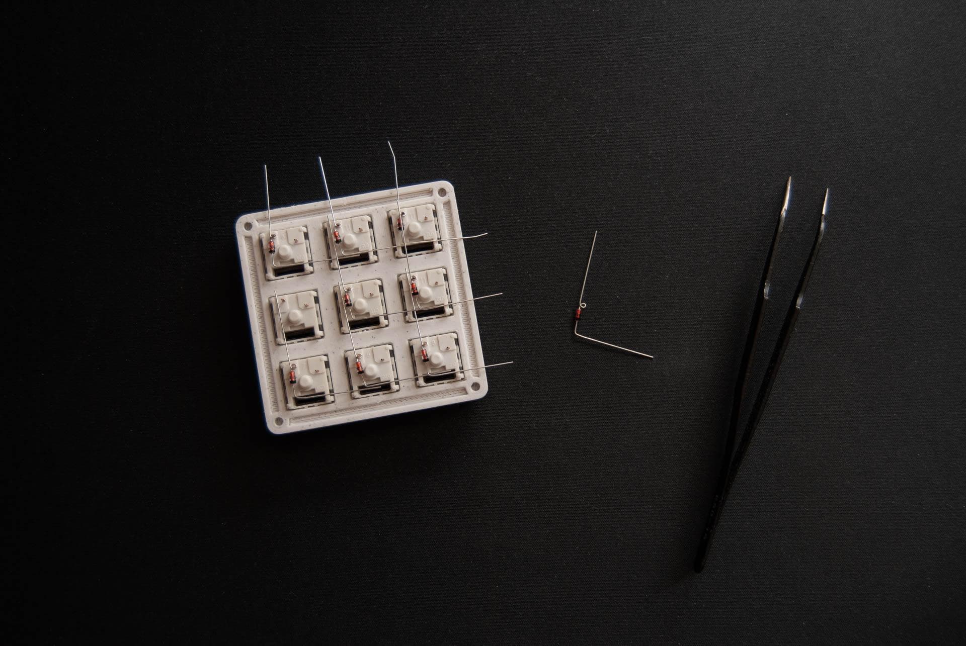
Diodes are two terminal components, an anode and a cathode, that conduct current in only one direction. The direction of flow is always from the anode to the cathode, and it's marked by a line near the cathode pin.
My personal choice for bending diodes is creating a loop on the anode side, that wraps around one of the switch pins, while the other terminal will be soldered to the next diode, thus forming a row and minimizing the ammount of wire needed. A pair of tweezers can be useful for this task.
3. Soldering the diodes and trimming the excess
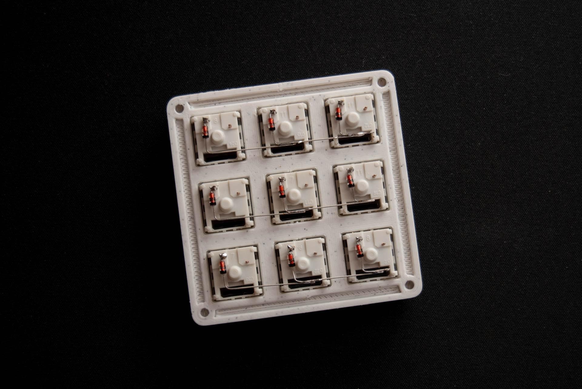
The diodes can have their terminals bent one row at a time, or the entire pad on one go, either way, when that step is done they can be soldered in; as described in the previous step the anode loop will be soldered around the switch pin, and the cathode leg will be soldered to the neighbouring diode.
NB: when you're handwiring a matrix make sure that you connect the cathode of a diode to the cathode of the next one in the row; wiring a cathode to an anode will make the controller not register your keypresses correctly.
Once all of the diodes are soldered, the excess terminals that have no use and are sticking out of the matrix can be trimmed.
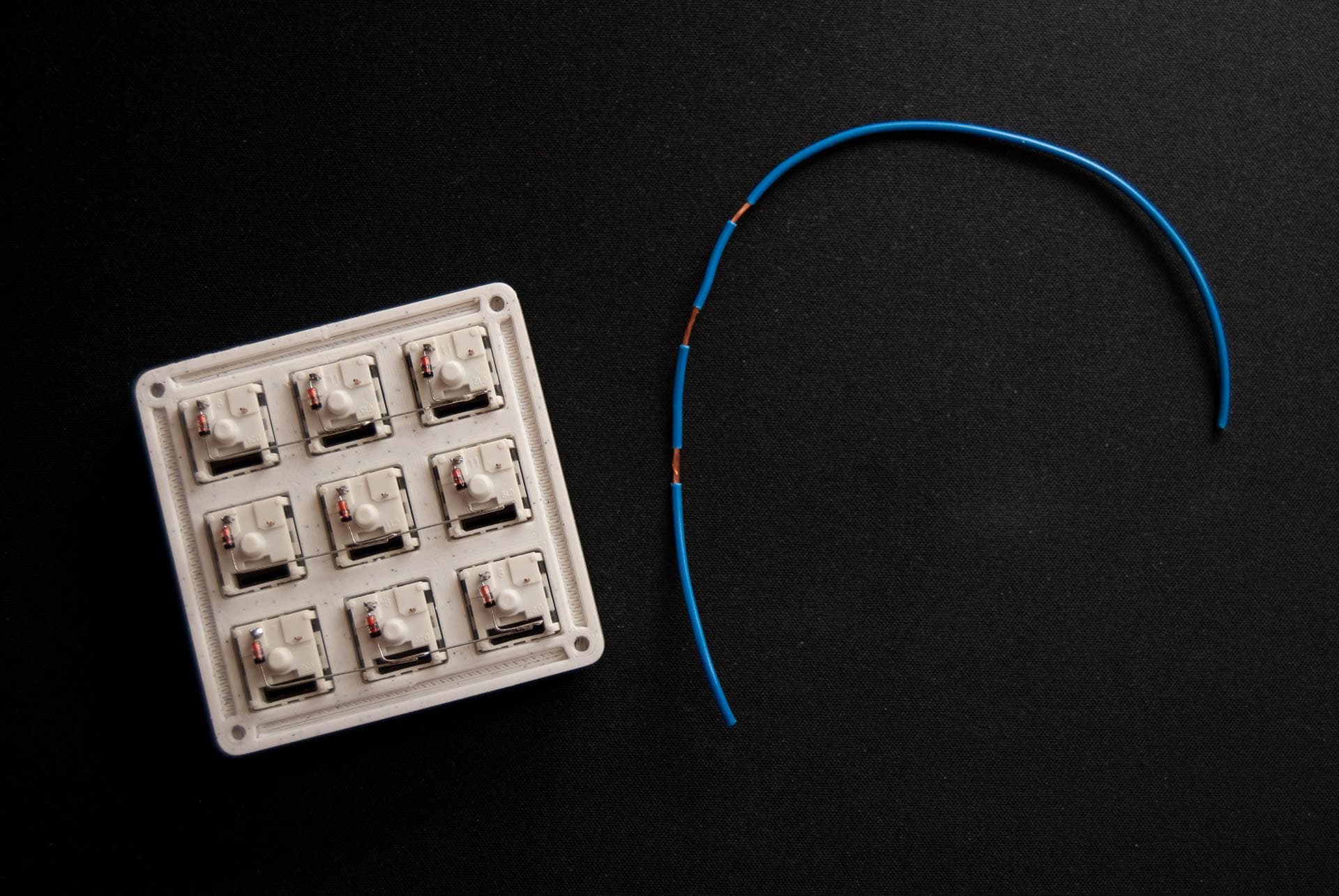
4. Pre-cutting the wires and stripping them for row/column wiring
A total of six wires will be soldered from the matrix to the controller. In order to form columns, pieces of wire will be measured and stripped like the one in the images below. Take your time and make sure that the spacing is right, make it as tidy as you can.
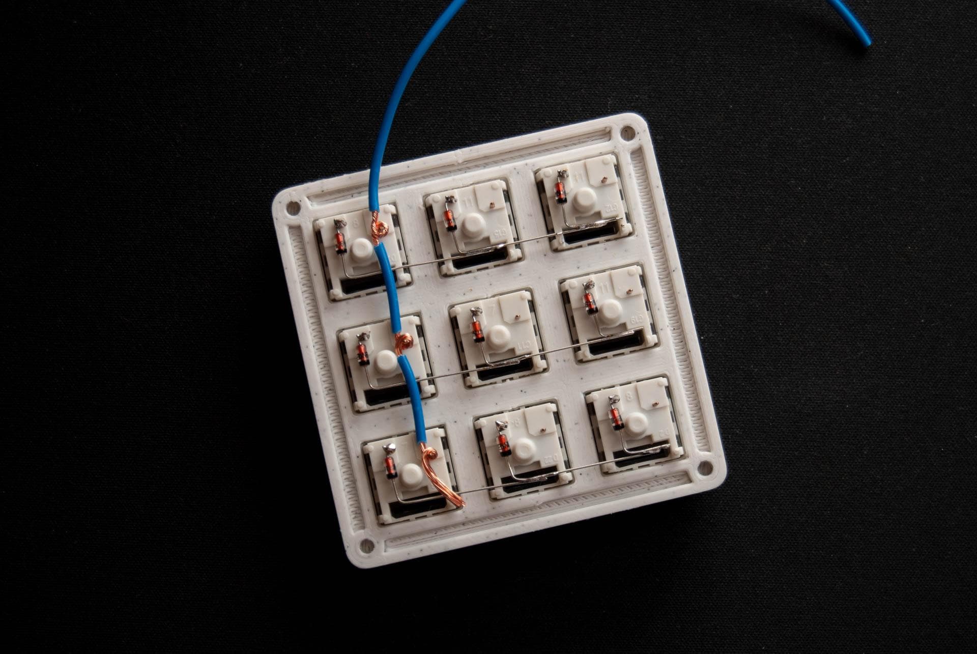
5. Wrapping the wires around the columns
The stripped parts of the wire will be looped around the pins of the switches, forming a column.
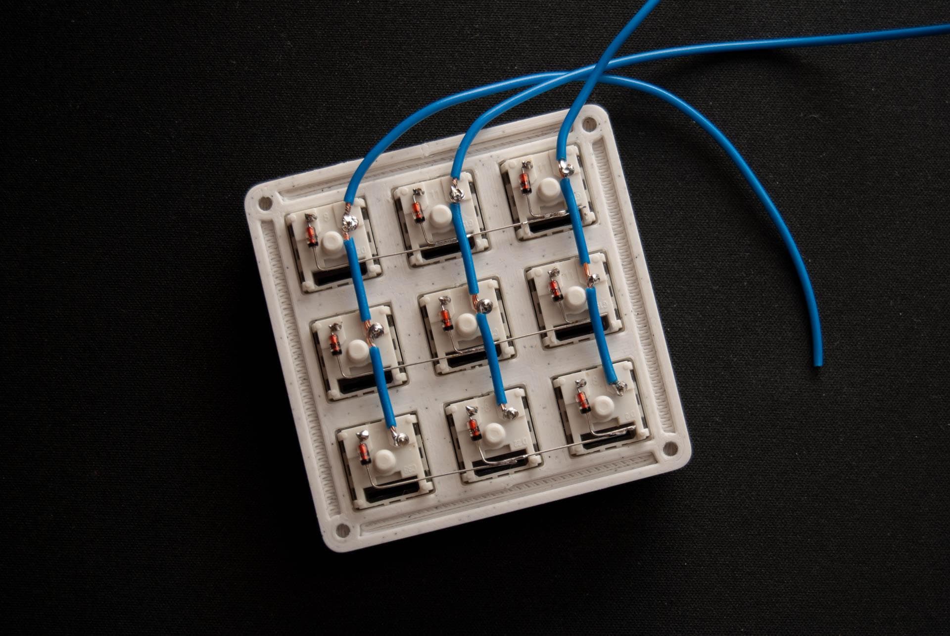
6. Soldering the column wires
The step above needs to be repeated for each column of the macropad, and then soldered in. Any excess wire that is leftover on the last switch of the column will be trimmed off.
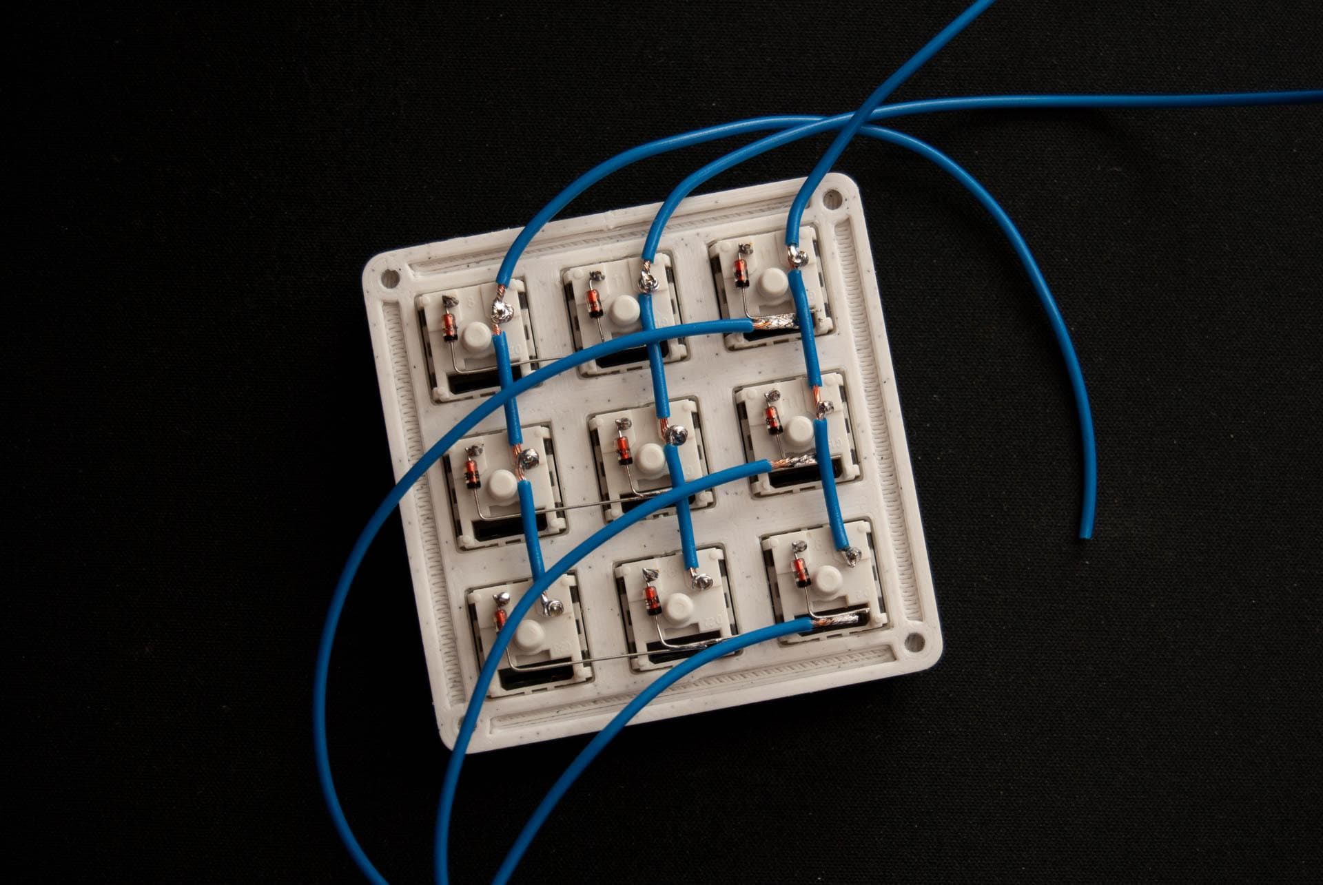
7. Soldering the row wires
Because we made use of the diode terminals to form the rows, we only need a piece of wire soldered to the cathode of any diode on each each of our three rows.
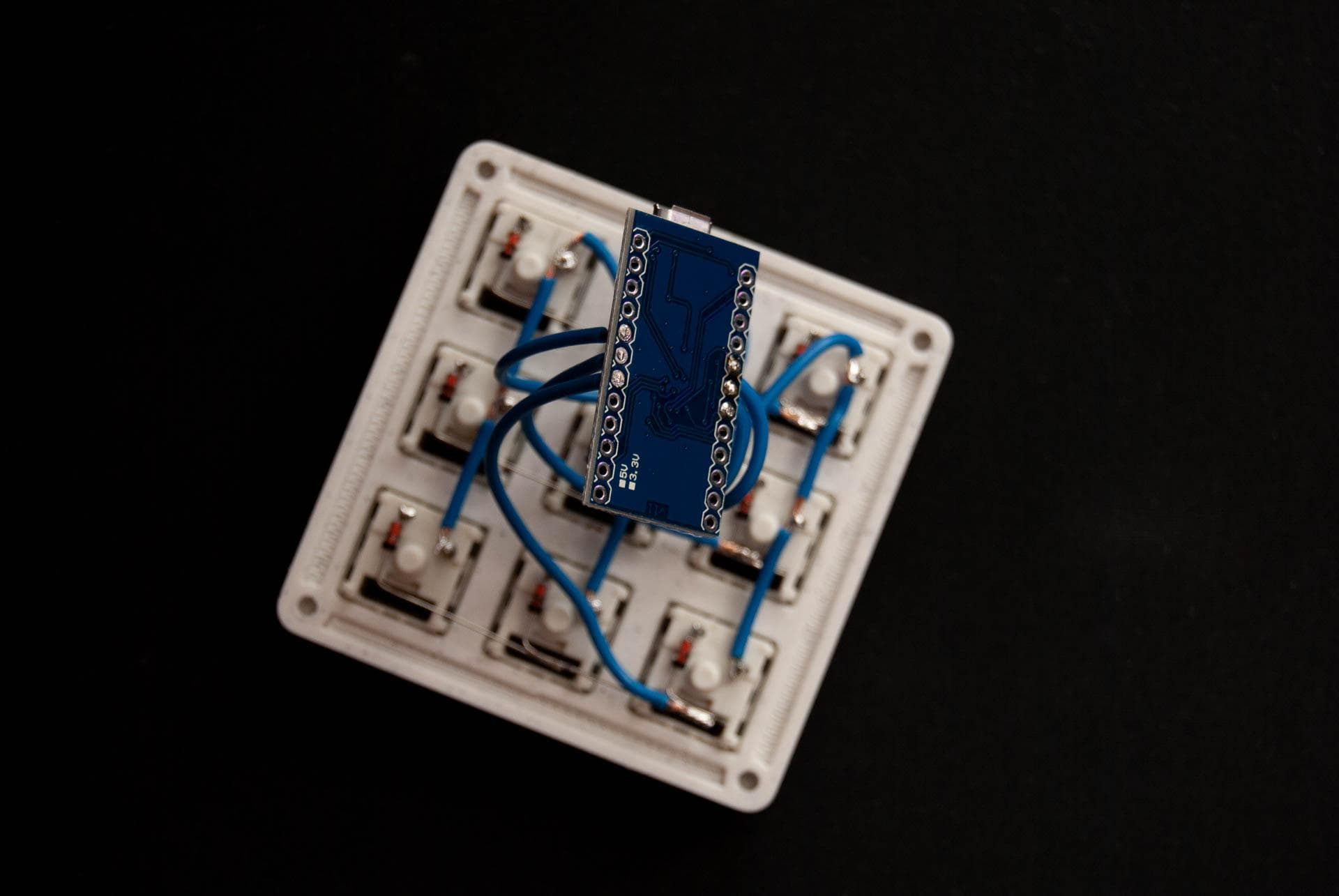
8. Soldering the Pro Micro
The wires from the matrix need to be soldered to their according pins on the Pro Micro. The firmware files can be modified for different wiring schemes but by default my fork is defined as it follows:
                      ROW0 	  ROW1 	  ROW2 	  COLUMN0 	  COLUMN1 	  COLUMN2

               PIN 	   F4  	   F5  	   F6  	     D1   	     D4   	     D0
Any excess wire sticking out of the back of the controller will be trimmed off.
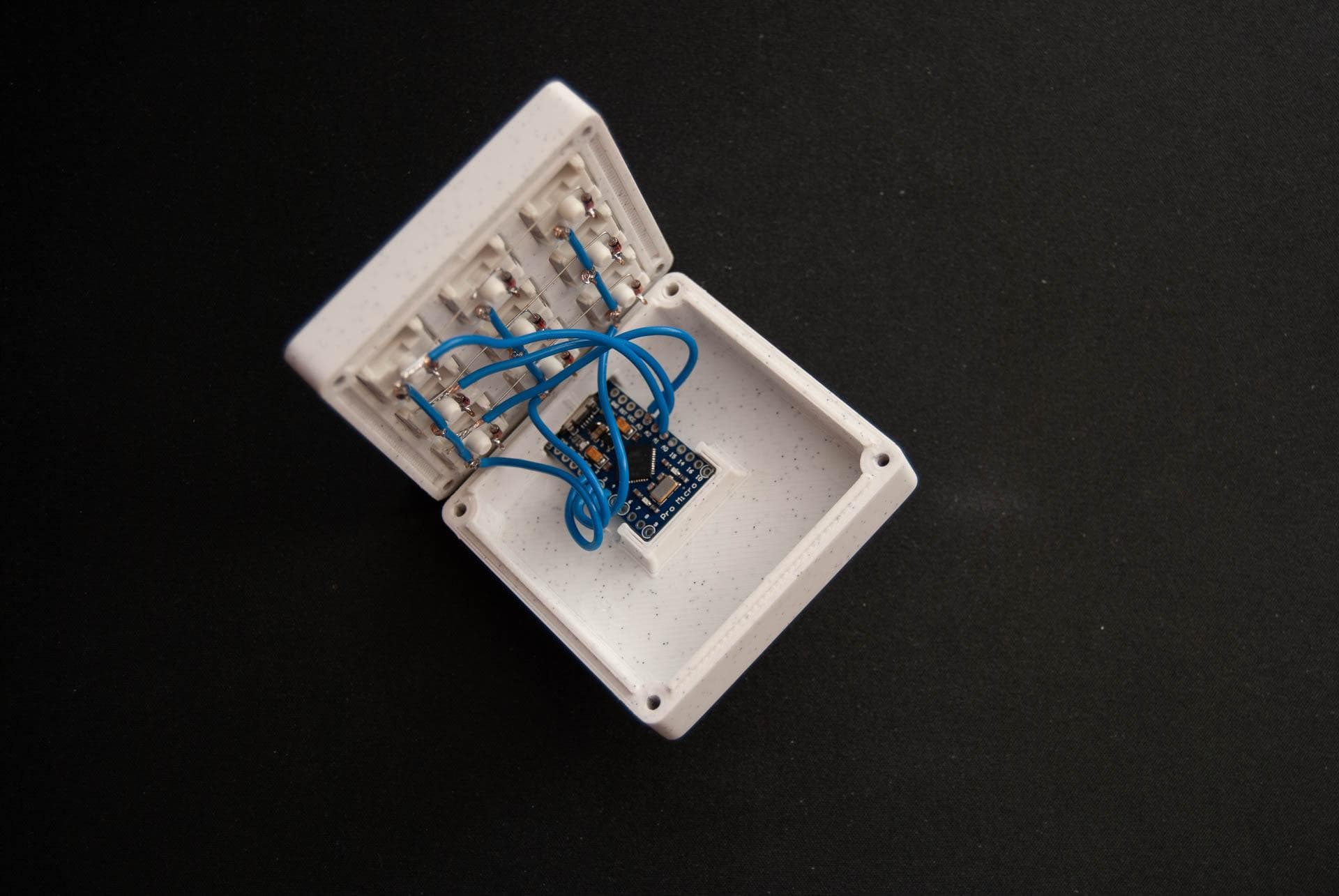
9. Inserting the Pro Micro into its slot
After the wires are soldered to the Pro Micro, the macropad can be plugged in and tested; if the VIA Keymap was compiled, the json definitions file can be loaded in the VIA Configurator and its integrated key tester can be used, alternatively the QMK Configurator test page.
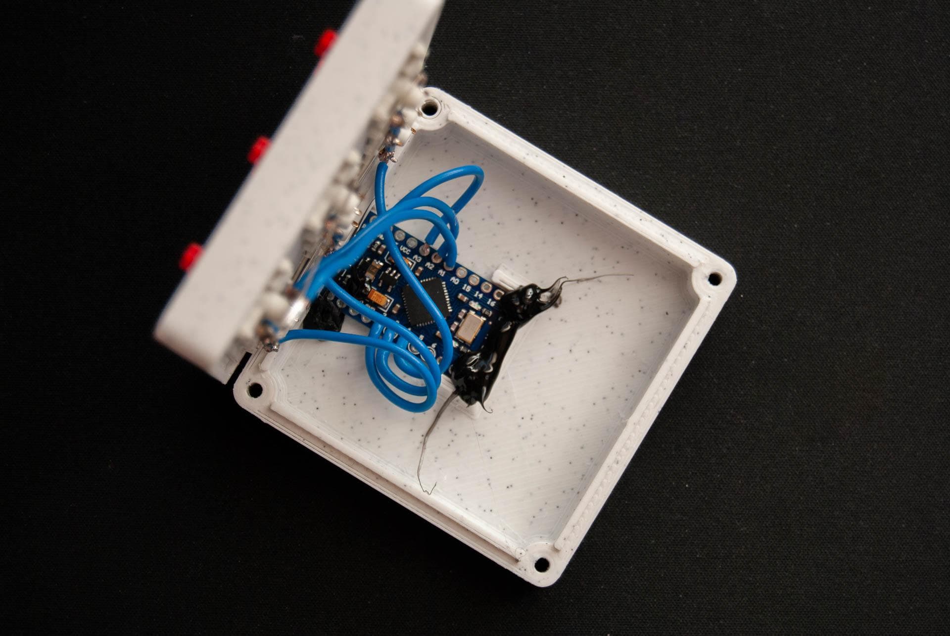
NB: If your material of choice for the case is rather translucent, the Pro Micro status LED can be covered with a dab of hot glue or anything that is opaque (such as electrical tape) so it doesnt shine through the case. Dont worry about the RX and TX LEDs as they are disabled in the firmware.
If everything checks out, the controller can be inserted into its slot.
10. Optional step - Gluing in the Pro Micro
If the controller feels loose, a dab of hot glue can be used to fix it in place.
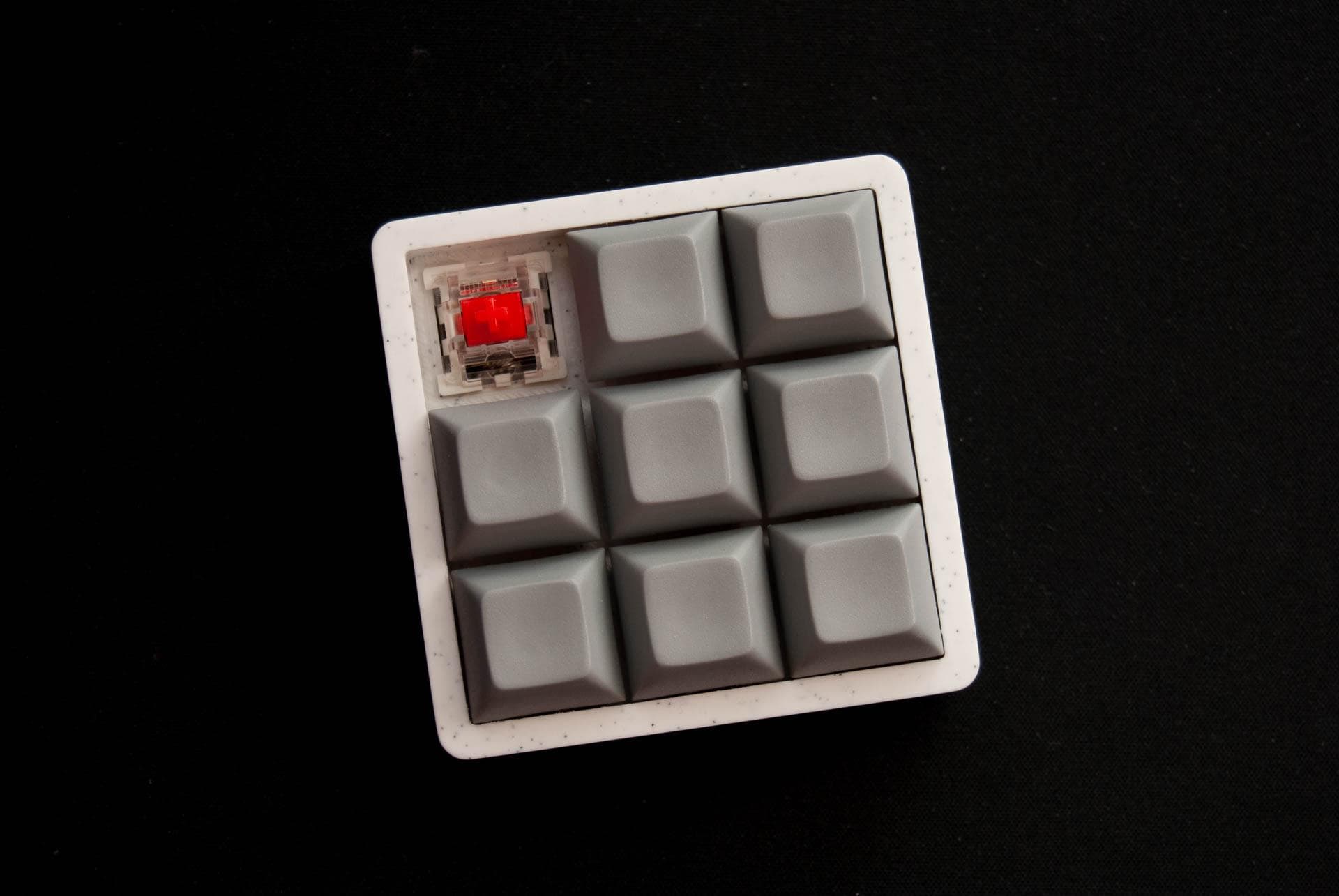
11. Fastening the bolts and adding the keycaps
Again, depending on the calibration of the 3d printer, the bolt head might feel tight when it's being threaded in.
NB: Overtightening the bolts might strip the top part and render the case useless.
The keycaps can be added at this point as the macropad is almost done.
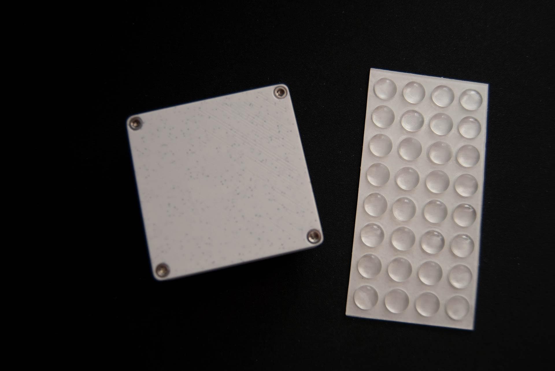
12. Adding bumpons to the bottom of the case
The last step is to add some bumpons to the bottom of the macropad, so it doesn't slide around on any surfaces that might be its new home; my favorites are 8mm ones.
13. Congrats! Assembly completed!
All done! The macropad is completely assembled, running QMK Firmware and ready to be put to good use!
Customize it and play around with different keymaps, until you find exactly whats working for you.
If you need any help at all, with any of these steps, dont hesitate to drop me a line using the form on the contact page page, and I'll do my best to get back at you asap.