VOID9 Macropad gets a PCB!
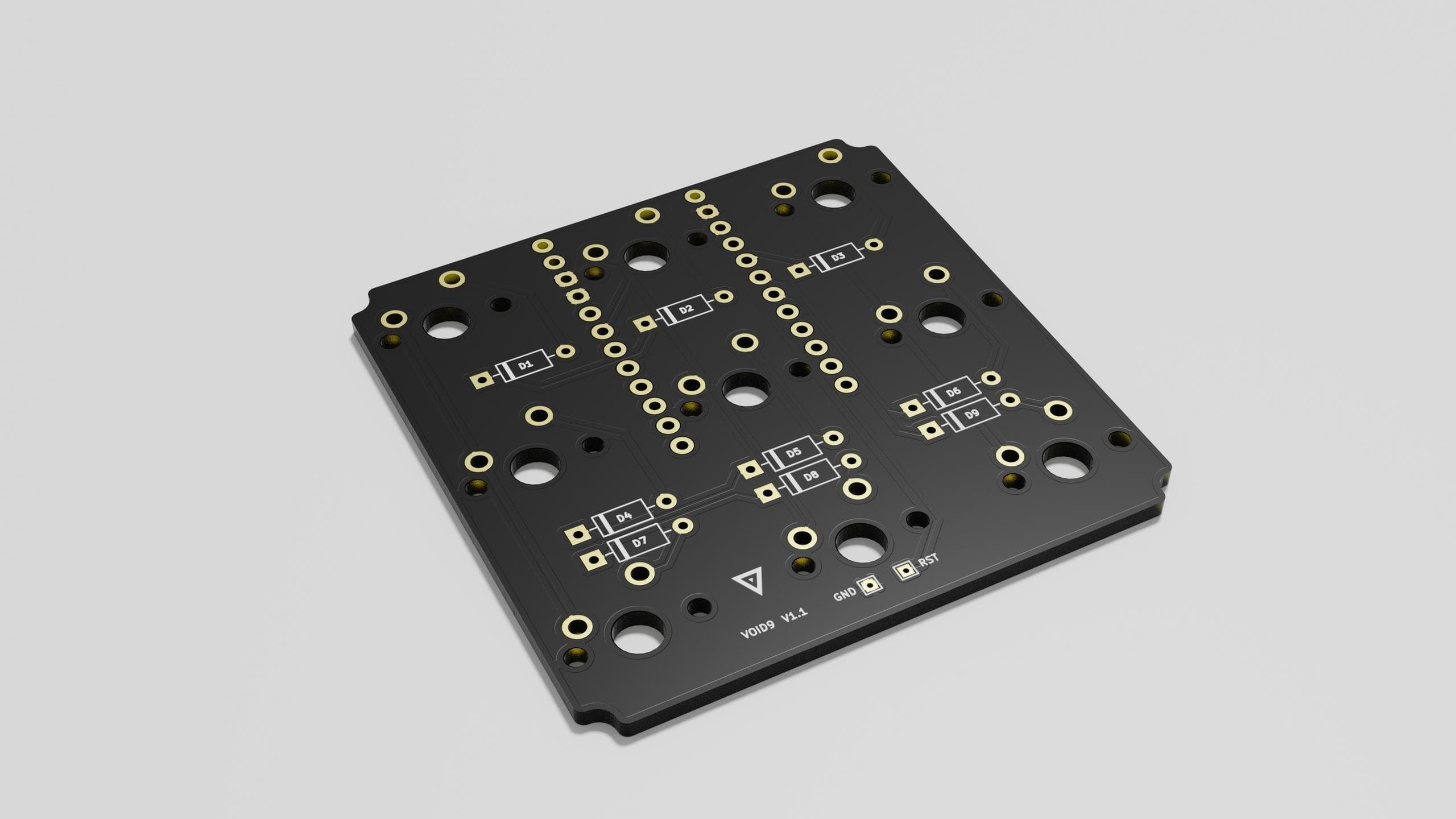
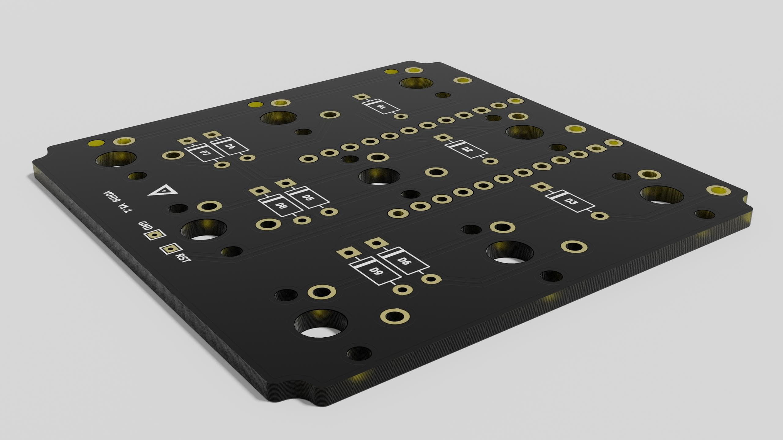
Handwiring is nice and everything, it's cheap, it's good practice for soldering, but it can become quite a handful, especially when it comes to buttoning up something more than a macropad; I decided that I should expand my skillset so I designed a pretty basic PCB for the smallest of my creations, the VOID9.

This is my first PCB, it's designed in KiCad and rendered in Blender; it supports 3 pin and 5 pin Cherry MX style switches, THT diodes and the Pro Micro is soldered using the pin headers that are usually included with these cheap clones. The PCB also features two pins on the bottom that can be shorted in order to reset the controller; I might work on a more accessible way to reset the macropad, if needed, even though the firmware supports starting into bootloader mode by holding down the key at row 0/column 0 pressed while plugging it in.
The PCB is somewhat compatible with the current version of the VOID9 by shaving the controller slot on the bottom case.
My current plan is to adjust the 3d models as it follows: remove the slot from the bottom part of the case, add a bevel to the port because the controller sits further back when its soldered to the PCB, and switch to M2 screws that will thread deeper and have a little bit more bite into the upper part of the case.

